Thermostat wiring plays a crucial role in ensuring your furnace operates efficiently and maintains comfortable indoor temperatures. Properly identifying where thermostat wires go on a furnace is essential for installation, repair, or troubleshooting. This guide provides an in-depth explanation of furnace thermostat wiring, wire colors, and terminal functions to help homeowners and technicians understand how to connect thermostat wires correctly.
| Terminal Label | Typical Wire Color | Function |
|---|---|---|
| R or Rh | Red (R) | Power from furnace (24V) for heating |
| Rc | Red (sometimes separate from Rh) | Power from furnace (24V) for cooling |
| W or W1 | White (W) | Heat call (signals furnace to heat) |
| Y or Y1 | Yellow (Y) | Cooling call (signals AC to turn on) |
| G | Green (G) | Fan control (signals fan to run) |
| C | Blue or Black | Common wire (provides continuous 24V power) |
Understanding Furnace Thermostat Wire Terminals
The furnace has a control board or terminal block where thermostat wires connect. Each terminal serves a specific purpose to regulate heating, cooling, and fan operation. Understanding these connections helps avoid wiring mistakes that may cause system malfunctions.
R, Rc, and Rh Terminals
The R terminal supplies 24-volt power from the furnace transformer. For systems with separate heating and cooling transformers, Rh (heating) and Rc (cooling) terminals are present, often connected via a jumper wire. The R wire from the thermostat connects to these terminals depending on system requirements.
W Terminal
The W terminal controls the heating function. When the thermostat calls for heat, it sends a signal through the white wire connected to W, instructing the furnace to activate.
Y Terminal
The Y terminal manages cooling. It sends a signal through the yellow wire to engage the air conditioning unit when cooling is requested.
G Terminal
The green wire connects to the G terminal, which controls the fan. When the thermostat signals the fan to run independently of heating or cooling, this wire activates the furnace blower.
C Terminal
The common wire, usually blue or black, connects to terminal C. It completes the circuit by providing a continuous return path for 24 volts, powering digital thermostats and enabling advanced programmable features.
Call 888-906-9139 for Free Local HVAC Quotes – No Obligation, Just Savings!
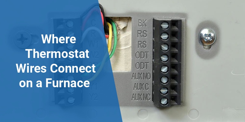
How to Identify Thermostat Wire Functions Using the Furnace End
Thermostat wires typically follow industry color standards, but variations exist. Examining the terminal labels on the furnace helps determine correct wire placement:
- Red (R or Rh/Rc): Power supply from furnace transformer
- White (W): Heating signal
- Yellow (Y): Cooling signal
- Green (G): Fan control
- Blue/Black (C): Common wire
Always verify wiring with a multimeter or consult manufacturer documentation, especially for newer or sophisticated HVAC systems.
Common Furnace Types and Their Thermostat Wiring Variations
Different furnace types may have slight wiring differences that affect thermostat connections:
| Furnace Type | Thermostat Wiring Notes |
|---|---|
| Gas Furnace | Typical 24V control with R, W, G, Y, and C terminals; digital thermostats require C wire for power |
| Electric Furnace | May have additional terminals for electric heat strips; common wire needed for advanced thermostats |
| Two-Stage Furnace | Often includes W1 and W2 terminals to control heat stages, ensuring efficient and gradual heating |
| Heat Pump Systems | Use additional terminals like O/B for reversing valve control and often separate Rc and Rh terminals |
Step-by-Step Guide To Connect Thermostat Wires to a Furnace
- Turn off power to the furnace to ensure safety during wiring.
- Open the furnace access panel to locate the control board or terminal strip with labeled connections.
- Identify the thermostat wires by color and match them to corresponding terminals: R/Rh, Rc, W, Y, G, and C.
- Remove any jumper wires between Rc and Rh if the thermostat has separate power wires.
- Connect the wires firmly into their respective terminals, ensuring no loose strands or poor contact.
- Double-check wiring by referencing the furnace’s wiring diagram and thermostat installation manual.
- Restore power and test the system by setting the thermostat to heating, cooling, and fan modes.
Troubleshooting Common Thermostat Wiring Issues
Incorrect wire placement or loose connections can lead to thermostat malfunctions such as:
- Furnace not responding to heat calls
- Fan running constantly or not running at all
- Cooling system not engaging
- Thermostat display losing power or resetting
Testing continuity with a multimeter and verifying voltage on R and C terminals helps isolate wiring faults. Clear labeling and color coding aid long-term system maintenance.
Upgrading to Smart Thermostats: Wiring Considerations
Smart thermostats often require a common wire (C wire) for continuous power to their internal electronics. If your existing furnace thermostat wiring lacks a C wire terminal, you may need to:
- Install a new common wire from the furnace
- Use a C wire adapter kit
- Choose compatible thermostats designed for system without C wire
Ensuring the correct connection of thermostat wires on your furnace enhances HVAC efficiency and allows full use of programmable or smart thermostat features.
Call 888-906-9139 for Free Local HVAC Quotes – No Obligation, Just Savings!