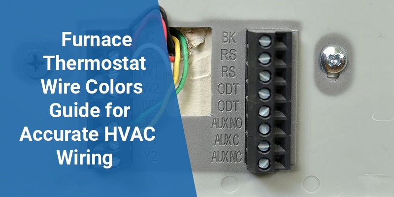
Identifying furnace thermostat wire colors accurately is essential for proper HVAC system installation and troubleshooting. Furnace thermostats use specific color standards to connect controls like heating, cooling, fan, and power signals. Understanding the common wire color codes and their functions helps homeowners and technicians avoid wiring mistakes that can damage equipment or impair heating and cooling.
| Wire Color | Standard Function | Optional Variations |
|---|---|---|
| Red (R) | 24V Power from Transformer | Rc (Cooling), Rh (Heating) Separate Power Lines |
| White (W) | Heating Control | W1 for First Stage Heat, W2 for Second Stage |
| Green (G) | Fan Control | Fan Relay Activation |
| Yellow (Y) | Cooling Control | Y1 for First Stage Cool, Y2 for Second Stage |
| Blue or Common (C) | Common Wire – 24V Return | Sometimes Black or Blue |
Standard Furnace Thermostat Wire Colors and Their Functions
Furnace thermostat wiring generally follows a color coding standard that assigns specific colors to distinct functions. The wiring connects the thermostat to the furnace control board and the transformer supplying low-voltage power.
Red Wire (R): Delivers 24 volts from the furnace transformer. Often split into Rc (cooling) and Rh (heating) terminals when separate transformers or power supplies are used.
White Wire (W): Controls the heating cycle. A single-stage furnace uses the W wire for heat, while multi-stage systems may use W1 and W2 to differentiate between heating stages.
Green Wire (G): Engages the furnace blower fan. It controls fan operation independently of heating or cooling.
Yellow Wire (Y): Activates the air conditioning or cooling system. Similar to heating, two-stage cooling uses Y1 and Y2 wires.
Blue or Black Wire (C): The common wire provides the continuous return path for 24-volt power, essential for powering modern digital thermostats.
Call 888-906-9139 for Free Local HVAC Quotes – No Obligation, Just Savings!
Common Wiring Configurations and Variations
Although color conventions exist, variations appear depending on furnace models, thermostat brands, and installation practices. Some systems:
- Use black as the common wire instead of blue.
- Separate heating and cooling power wires (Rh and Rc) with jumper wires linking them when a single transformer controls both.
- Have additional wires like O/B for heat pump reversing valves.
Technicians should always verify wire functions with schematics or a multimeter before making connections to avoid damage or incorrect operation.
How Furnace Thermostat Wires Connect to HVAC Components
| Wire Color | Thermostat Terminal | HVAC Component Controlled |
|---|---|---|
| Red (R, Rh, Rc) | R, Rh, Rc | 24V Transformer Power |
| White (W, W1, W2) | W, W1, W2 | Heating Relay |
| Yellow (Y, Y1, Y2) | Y, Y1, Y2 | Cooling Compressor |
| Green (G) | G | Fan Relay |
| Blue or Black (C) | C | Transformer Common |
The wires carry low-voltage control signals from the thermostat to the furnace’s control board or air handler. Each signal wire triggers a relay to start heat, engage the compressor, or run the blower fan.
Identifying and Testing Thermostat Wires
When working on furnace wiring, identifying each wire is crucial. Use these tips:
- Visual Inspection: Color codes often indicate function; verify by tracing wires to their origin or using the furnace schematic.
- Multimeter Testing: Check for 24 volts AC between the R and C wires to confirm power supply.
- Continuity Tests: Between a control wire and the furnace control board terminals to verify connections.
- Use a Wire Labeler: Label wires during removal to ensure correct reconnection.
Modern Thermostats and the Importance of the C Wire
Traditional mechanical thermostats did not require a common wire (C wire) because they relied on battery power or intermittent transformer voltage. Modern programmable and smart thermostats need a consistent 24V supply, which the C wire provides.
Without a C wire, many advanced thermostats experience power issues or require additional adapters to function correctly. Always check whether a C wire exists before installing smart thermostats. If missing, installers might use a power extender kit or run an additional wire.
Color Codes for Heat Pump Thermostat Wiring
Heat pump systems introduce extra wires not found in conventional systems. Common colors and functions include:
Call 888-906-9139 for Free Local HVAC Quotes – No Obligation, Just Savings!
- O or B Wire: Controls the reversing valve to switch between heating and cooling mode.
- Auxiliary Heat Wires (E or W2): Engage backup heat strips or auxiliary heating stages.
- L Wire: Sometimes used for diagnostics or system monitoring lights.
Knowing these additional wires is essential for connecting heat pump thermostats appropriately and avoiding errors.
Tips For Safe Furnace Thermostat Wiring
- Turn Off Power: Always switch off the furnace power before working on wiring.
- Use the Furnace Manual: Reference the wiring diagram to ensure proper connections.
- Match Wire Functions, Not Just Colors: Wire colors can vary; confirm roles using proper tools.
- Secure Connections: Loose wires can cause malfunctions or hazards.
- Hire Professional Help: When unsure, consult a licensed HVAC technician to ensure safety and compliance.
Summary Table of Furnace Thermostat Wire Colors
| Wire Color | Primary Function | Common Variations | Typical Thermostat Terminal |
|---|---|---|---|
| Red (R, Rc, Rh) | 24V Power Supply | Separate Rc/Rh in dual transformer systems | R, Rc, Rh |
| White (W, W1, W2) | Heating Control | Multi-stage heating uses W1/W2 | W, W1, W2 |
| Yellow (Y, Y1, Y2) | Cooling Control | Two-stage cooling uses Y1/Y2 | Y, Y1, Y2 |
| Green (G) | Fan Control | Activates blower fan | G |
| Blue or Black (C) | Common Return Wire | Sometimes black or blue used | C |
| Orange/Blue (O/B) | Heat Pump Reversing Valve | O energizes in cooling, B energizes in heating | O or B |
